


Preface:
The methyl methyl ester unit of an acrylonitrile factory was built with the technology provided by a German company. Among them, the Hastelloy C22 amide heater ruptured and leaked many times after being used for 10 months, and it happened again about 20 days after each welding repair leaked, had to be replaced after only a year of operation.
In order to clarify the form, nature, and cause of damage and rupture, propose repair and improvement technologies, carry out relevant test and analysis work, and participate in the whole process of repair and transformation. This article focuses on restoration and renovation techniques. This work has important reference value for the construction and operation of methyl methyl ester plant. This work shows that even if high-nickel alloys such as Hastelloy C22 with high chromium and molybdenum content and excellent corrosion resistance in oxidizing, reducing and oxidizing-reducing media are used, if the manufacturing process is not proper, it is still unavoidable. Early failure.
1 Overview of Amide Heater:
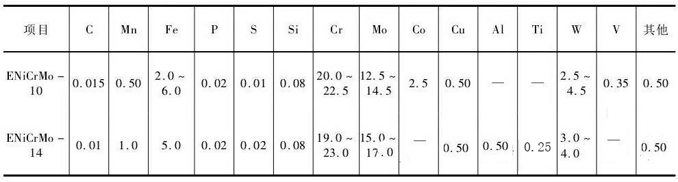
The amide heater has a double-coil structure (see Figure 1), with a total of 10 layers, the core diameter of the outer coil tube is φ1508 mm, and the core diameter of the inner coil tube is φ1258 mm. The specification of the coil is φ114 mm×3 mm, the total length is 90,000 mm (connected by dozens of girth welds), the material is Hastelloy C22, and the welding material is ENi Cr Mo-10. The inner diameter of the coil embedded container is φ1042 mm, the wall thickness is 24 mm, and the material is S31603 (316L).
Amide heater operating parameters: inside the tube: working pressure 0.5MPa; working temperature 105.5/156°C; medium: amide solution, containing sulfuric acid, ammonium bisulfate, water, acetone, intermediate products, and other organic substances, with strong reducing and oxidizing properties[ 2] , especially the problem of high-temperature dilute sulfuric acid corrosion; inside the container: working pressure 0.95 MPa, working temperature 210/184 ℃, medium steam. The corrosion margin of heat exchange tubes and containers are both 0.
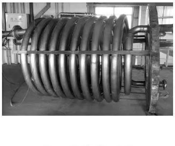
Figure 1 Appearance of amide heater
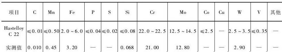
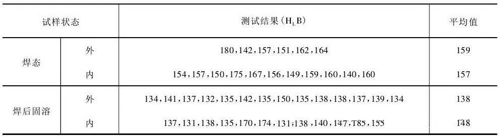
The components of the heat exchange tubes have been tested to meet the requirements of relevant standards, as shown in Table 1.
Table 1 Chemical composition of heat exchange tube base materials and welding materials %
2 Damage detection and analysis
2.1 Damage detection
The test found that the coil had serious corrosion damage, which caused rupture and leakage.
The details are as follows.
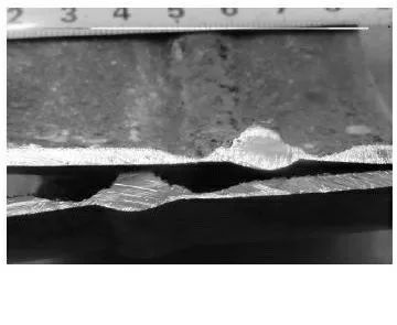
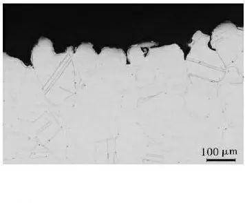
Figure 2 Appearance of corroded grooves in the heat-affected zone 1 (1)
The heat-affected zone on both sides of the circumferential weld of the coil is severely corroded and thinned, forming an annular corrosion groove. The width of the groove is about 10-15 mm, and the remaining wall thickness at the bottom is only 0.1-0.5 mm. Holes appear one after another in the severely corroded parts, resulting in leakage. Almost all butt ring seam areas of coils have such corrosion damage, see Figures 2 and 3.
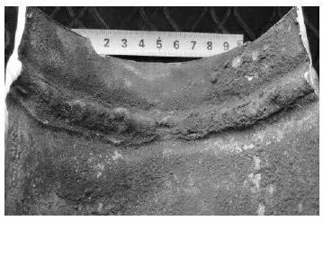
Figure 3 Appearance of corroded grooves in the heat-affected zone 2 (2)
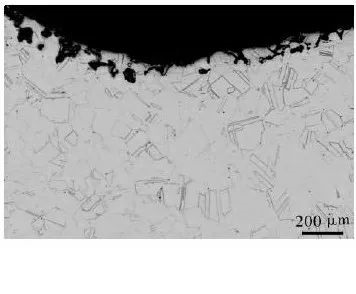
The local weld metal corrodes, forming pit-like or strip-like depressions, see Figure 4.
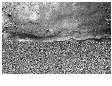
Figure 4 Corrosion appearance of weld seam
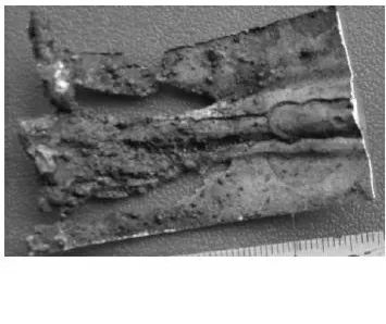
(3)The pipe under the ring for repair (the ring covering the outer wall of the leaking pipe, the two ends of which are connected to the pipe by fillet welds) is severely corroded, the wall thickness is severely thinned, and large strip-shaped corrosion grooves and holes appear , or even fester, see Figures 5 and 6.
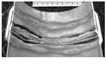
Figure 5 Corrosion appearance under the collar 1
3 Countermeasures 3.1 Ideas for dealing with corrosion damage
(1) It can be seen from the inspection and analysis that the method of adding an external casing cannot be used for repair. Because of the welding heat, secondary heating, and gap effect, the repaired area is corroded faster, and the coils below it are generally corroded and festered (see Figure 6); moreover, after each repair with casing, run Corrosion leakage occurred again in only about 20 days.
(2) Use the method of cutting off all the ring seams and heat-affected zones (pipe sections) of the coil with serious corrosion damage, reassemble and weld. The reason is that the wide range of heat-affected zones on both sides of the weld has been corroded and thinned into grooves, or has leaked; and the material in this zone has been severely sensitized, so it is difficult to repair it with the usual repair welding method after removing defects by grinding.
(3) The overall solution treatment after welding is adopted. Under the current operating conditions, the biggest problem of the C22 coil heater is that, due to the action of welding heat, severe trench corrosion occurs in a large area in the area of the sensitizing temperature range. The overall solution treatment after welding can re-solutionize the rich Mo, Cr carbides and Ni-Mo intermetallic compounds precipitated during the welding process in the joint area, improve the composition segregation in the weld metal, and eliminate the adverse effects of cold deformation , Therefore, it is possible to fundamentally improve the joint area and the overall corrosion resistance of the coil.
(4) Technological transformation of the heater. In order to solve the overall serious corrosion and thinning problem of the amide heater and prolong its service life, it is proposed to increase the wall thickness of the coil from 3.00 mm to 6.00 mm after necessary demonstrations and tests (accounting shows that this change does not affect the original replacement. Thermal effect[1] ); In order to solve the serious intergranular corrosion problem in the sensitized zone, the overall solid solution treatment is carried out after the heater is welded.
(3) Metallographic test
The tissues of various parts of the butt ring seam area of the C22 pipe after solution treatment are shown in Figures 11-15. Figures 11 and 12 show the weld metal structure, that is, austenite. The former (near the fusion line) is cast columnar crystals; the latter (weld core) is equiaxed dendrites, but the grain boundaries and dendrite junctions are relatively Fuzzy, many grain boundaries have been dissolved. Figure 13 shows the microstructure of the fusion zone. The equiaxed grain boundaries on the base metal side are incomplete, and most of the columnar or dendritic grain boundaries on the weld side have been dissolved. Figure 15 shows the microstructure of the substrate, which is equiaxed and twinned, and the grain boundaries are fine and not obvious. Obviously, there is little precipitation at the grain boundaries [13].
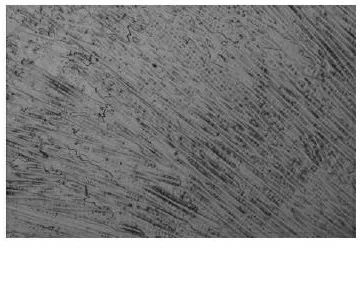
Fig. 1 1 Solid solution pipe weld 1 100×
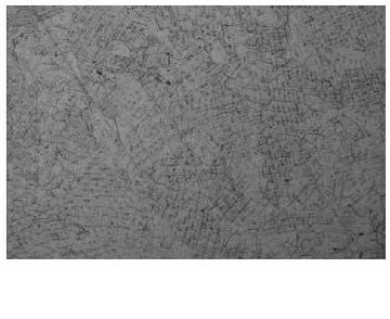
Figure 1 2 Solid solution pipe weld 2 100×
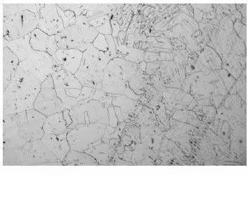
Figure 1 3 Fusion line of solid solution pipe 100×
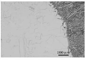
Figure 1 4 Heat-affected zone of solid solution pipe 100×
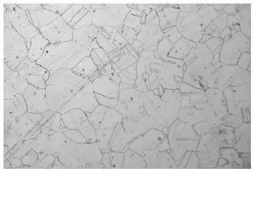
Figure 1 5 solid solution tube substrate 100×
For comparison, the organization of the corresponding position (weld metal, fusion zone, base material) of the running pipe is shown in Figures 16-20. Through comparison, it can be seen that the weld seam, heat-affected zone and base material structure of the solid solution pipe are thicker than the corresponding zone of the operating pipe, and the grain boundary of the operating pipe is thicker and clear; Partial disappearance of the grain boundaries in the grain region; most of the columnar grain boundaries on the side of the weld in the superheated zone of the solid solution tube disappear, and the austenite grain boundaries on the side of the base metal are incomplete. The above shows that after solid solution treatment after welding, the microstructure has changed significantly, and the precipitates in the joint sensitization temperature zone can be redissolved, which also has a significant effect on the weld metal composition, microstructure homogenization and elimination of cold deformation [13].
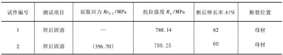
Based on the above tests, it can be concluded that after the solution treatment after welding, the uniformity of the composition and structure of the welded joint area of the C22 pipe has been fundamentally improved. From the hardness test, solid solution is also of great benefit in eliminating the influence of cold deformation.
3.4 Project implementation
(1) For the severely corroded operating pipes, two coil heaters were repaired using the method described in Section 3.2.
(2) Retrofit the C22 amide heater using the method described in Section 3.3. That is, the wall thickness of the remanufactured coil is increased to 6.0 mm; the coil is assembled and welded by TIG process; after welding, the overall solution treatment is carried out, and the heating temperature is 1115~1130 °C. An electric heating furnace is used for solution treatment. If gas heating is used for heat treatment, heating and cooling in a reducing atmosphere should be strictly controlled [14], and the flame should not be in direct contact with the component, otherwise, the metal may be embrittled and even cracked; dry nitrogen and argon can also be used for Protective atmosphere: The sulfur content in the combustion atmosphere should be strictly controlled and confirmed by relevant testing [14-16] to avoid severe high temperature (>635°C) sulfidation corrosion. The modified amide heater has been running for more than two years without any problems and works well.
4 Conclusion
(1) The rupture and leakage of Hastelloy C22 coil amide heater in the methyl ester unit within a short period of time is mainly caused by severe corrosion damage in the welding zone.
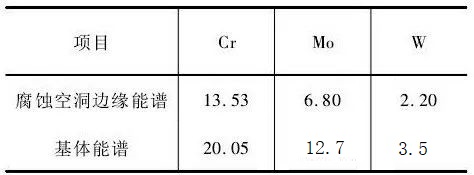
(2) Due to the action of welding heat, the material in the welded joint area precipitates carbides or intermetallic compounds rich in Cr and Mo, making the surrounding matrix poor in corrosion-resistant elements, which is the main factor leading to severe corrosion. Therefore, under the operating conditions of the heater, Hastelloy C22 still has the risk of “material sensitization”. Deformation and erosion accelerate corrosion.
(3) The method of adding casing should not be used for repair. Because of the welding heat, secondary heating, and interstitial effect, the repaired area will be corroded faster. It is recommended to use the method of cutting the circular seam and its heat-affected zone, reassembling, and welding for repair.
(4) Regardless of welding production or repair, post-weld solution treatment is the key link to solve serious corrosion problems. It will enrich the Mo in the joint area, re-solutionize the Cr precipitated phase, and homogenize the composition and structure of the joint area. Eliminate the adverse effects of cold deformation, so it will fundamentally improve the corrosion resistance of the joint area and the overall coil.
Post time: Jul-15-2023


